R.NET USB interface (by Lasse OH3HZB and Veli-Matti OH7JEV) is an audio/CTCSS/PTT/squelch USB interface designed especially for (R.NET) repeater use.
COMMERCIAL USE STRICTLY FORBIDDEN (KORTIN JA PIIRILEVYDESIGNIN KAUPALLINEN KÄYTTÖ EHDOTTOMASTI KIELLETTY)
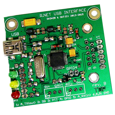
R.NET USB interface is based on C-Media CM108/CM119 USB audio chip that has some integrated GPIO. Operational amplifiers (op-amps) are on the bottom side of the PCB for audio signal buffering and level adaptation. Places for audio level adjustment trimmer potentiometers can be seen in the picture.
Pin headers exist both for LEDs and input-output connections to allow different enclosure options. SUB-D connector chassis is grounded and holes in the upper corners can be grounded by short-circuiting SMD jumpers on the bottom side of the PCB.
Suggested LED colors are shown in the picture: PWR green, AUDIO is yellow and PTT is red.
D9 connector / pin header pinout
- pin1: TX audio (out)
- pin2: Squelch
- pin3: PTT
- pin4: GPIO
- pin5: RX audio (in)
- pin6: GND
- pin7: Not connected
- pin8: GND
- pin9: GND
Schematic (rev.B)
rnetdongle revB schematic (pdf)
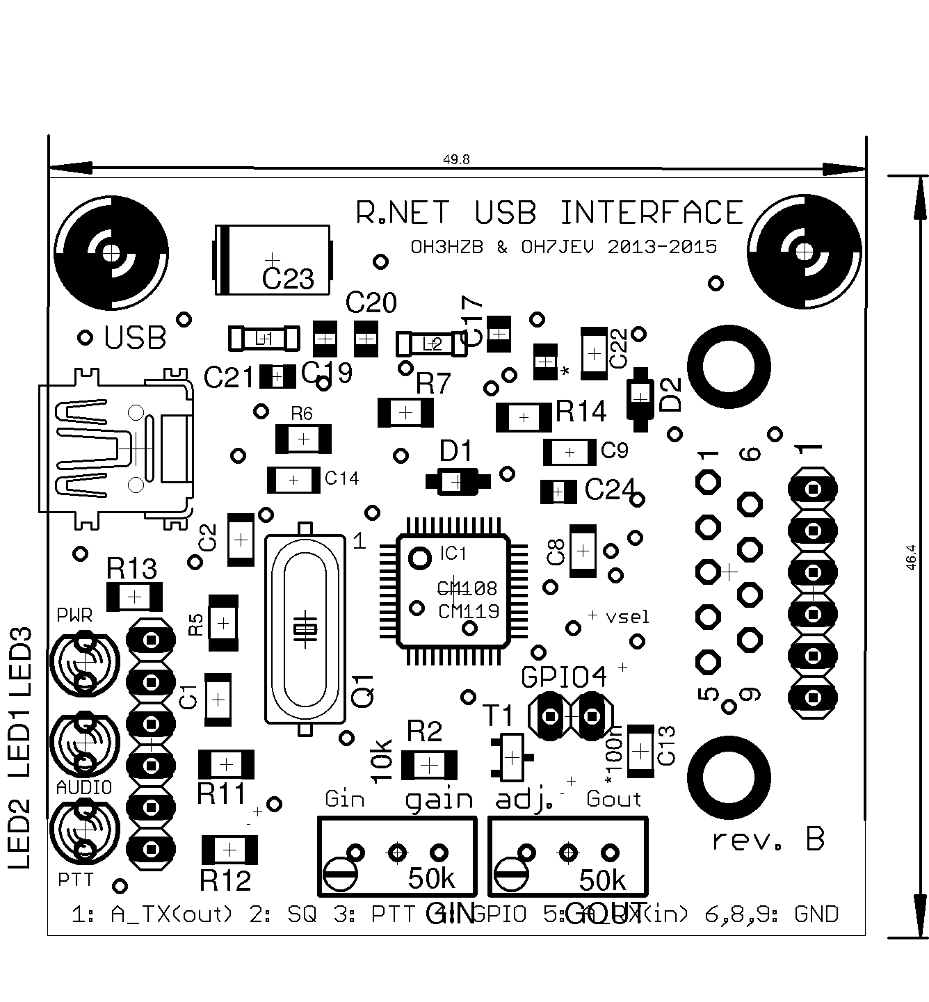
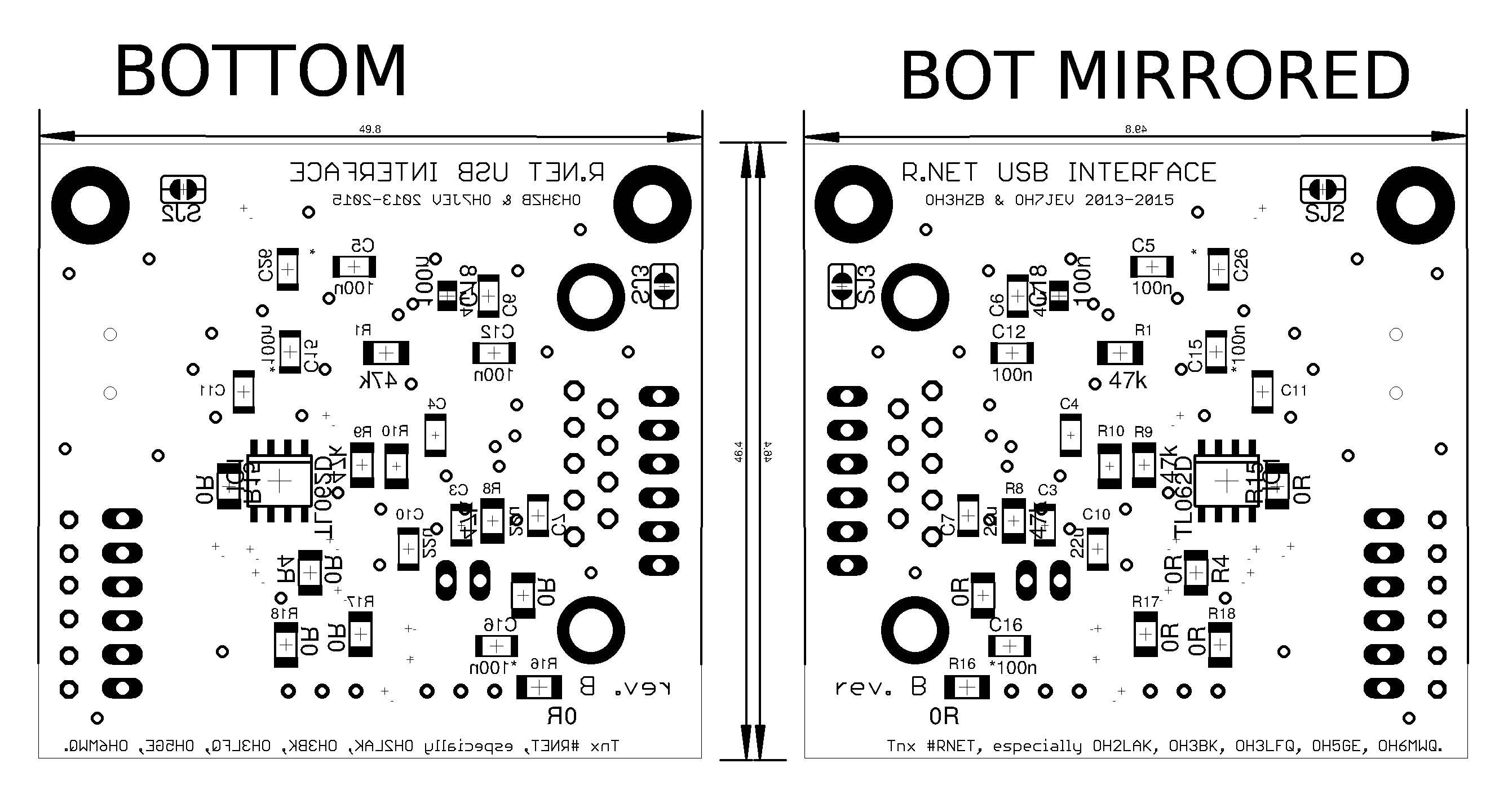
Component values and placement (rev.B)
- C1,C2: 20p
- C3,C6,C8,C9,C23: 4u7
- C4,C7,C10,C11: 22u
- C5,C12..C22,C24 100n
- L1,L2: e.g. 1 mH
- R2: 10k
- R5: 1M
- R6,R7: 22
- R1,R8,R9,R10: 47k
- R11,R12,R13: 150..330 (depending on led brightness)
- R14: 1k5
- R3,R4,R15..R18: 0
- GIN,GOUT: 50k trimmer
- D1,D2: 1N4148 smd
- LED1: YELLOW,3mm
- LED2: RED, 3mm
- LED3: GREEN, 3mm
- T1: BC848 or BC847 or similar (NPN)
- IC1: TL062 or LM258 or similar
- Q: 12M
- USB connector: mini-USB
Placement diagrams:
Datasheets
Local copies of CM108 and CM119 datasheets: (TODO: LINKS)
Credits
TNX #RNET, especially OH2LAK, OH3BK, OH3LFQ, OH5GE and OH6MWQ.