TheLinkBox software delivered with the R.Net Raspbian Linux is compiled with special Raspberry Pi GPIO support.
The GPIO ports can be used as radio port PTT and COS signals to interface with the connected radio and also to radio port PL (CTCSS) detection signal from an external CTCSS decoder. Furthermore, available GPIO pins can be used to control radio squelch level, steer channels etc.
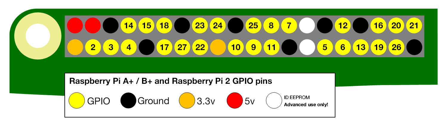
Raspberry Pi GPIO PL/CTCSS input
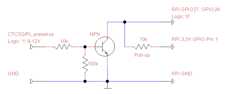
A simple transistor buffer circuit can be used to interface the Raspberry Pi GPIO pin input to a radio PL/CTCSS detector circuit. The circuit expects that the PL/CTCSS signal provided is active high.
In the example R.Net TheLinkBox port configuration file /etc/thelinkbox/port1-GPIO.conf GPIO pin 27 is configured as PL/CTCSS input pin. Respectively the same pin is initialized as input pin in the Rpi_GPIO_setup.sh -script
GPIO pin 27 is nicknamed as CTCSS1 to be used with the first radio port, GPIO pin 24 is nicknamed as CTCSS2 for the optional second radio port.
TheLinkBox GPIO PL/CTCSS port configuration
The port-specific PL/CTCSS port is configured in the port configuration file (example /etc/thelinkbox/port1-gpio.conf). The port configuration file is then configured in TheLinkBox general configuration file /etc/thelinkbox/tlb.conf to be loaded up during TheLinkBox startup.
Two parameters in the port configuration file effect the PL/CTCSS input port media and port number;
RxCtcssMethod = 9 selects the Raspberry PI GPIO port mode;
; The following variable selects the method thelinkbox will use to determine
; if a CTCSS tone is present on a received signal. Note: must use the same
; hardware interface as RxCosMethod, i.e. if the RxCosMethod is a line on
; the serial port then RxCtcssMethod must be a different line on the same
; serial port.
; 0 - none
; 1 - Software CTCSS decoder
; 2 - Parallel port (IRLP interface)
; 3 - serial port CTS
; 4 - serial port DSR
; 5 - serial port DCD
; 6 - device supporting /dev/input such as USB HID (Linux only)
; 7 - USB device GPIO (use method 6 for the iMic)
; 8 - PCF8754 I2C port expander on iMic
; 9 - Raspberry Pi GPIO /sys/class/gpio/... method
RxCtcssMethod = 9
GpioSysClassID = 17 defines GPIO port 17 to be the PTT output port;
; For Raspberry Pi GPIO method, define the GPIO port number for PL input
; For example 27 for Port1 and 24 for Port2
GpioSysClassId_PL= 27
To enable correct polarity of the PL/CTCSS signal (active low), a invert parameter is set active;
By default (without the variable ‘InvertCTCSS’ set active, the signals are active high but with Raspberry Pi 3.3V TTL logic, this is difficult to arrange due to expected higher voltage levels of connected peripherals. A buffer circuit is recommended to protect the GPIO ports from overvoltage.
; Set this variable to invert the sense of the CTCSS_Bit
; For Raspberry GPIO, inverted sense means Logic '0' is active state
InvertCTCSS = 1